I once sat in a humid, windowless inspection room in Shenzhen, staring at a batch of “precision” components that looked more like expensive scrap metal than the parts our engineers had drawn. The designer had insisted on internal square corners and tolerances tighter than a drum, convinced that a high-end machine shop could just make it happen. They couldn’t. What they actually did was triple our lead time and blow the unit price out of the water because nobody had bothered to learn how to design for CNC with actual manufacturability in mind. Most people treat a CAD model like a wish list, but in the real world, a design that ignores the physical limitations of a cutting tool isn’t a masterpiece—it’s a financial liability.
I’m not here to give you a theoretical lecture on geometry or a sanitized list of textbook best practices. I want to show you how to bridge the gap between a pretty digital model and a cost-effective, shippable part. We are going to look at the specific, practical ways to optimize your geometry so you aren’t handing your margin over to the machine shop through unnecessary setups and tool changes. I’ll show you where to loosen your tolerances and where to simplify your features, ensuring that when your quote finally lands on my desk, it’s actually achievable.
Table of Contents
Optimizing Part Geometry for Milling Without Breaking the Bank
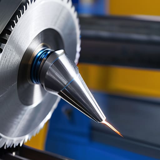
When I’m reviewing a quote for a new component, I’m not just looking at the material volume; I’m looking at how much the geometry is going to fight the machine. If you design deep, narrow slots that require tiny, long-reach end mills, you are essentially asking for trouble. Those slender tools lack rigidity, and unless you want to pay for the inevitable scrap caused by minimizing tool deflection issues, you need to rethink those proportions. A part that looks elegant on a screen often becomes a nightmare of vibration and chatter once it hits the spindle.
True design for manufacturing principles dictate that you respect the physical reality of the tool. I’ve seen too many engineers specify internal radii that are far too tight, forcing the shop to use specialized tooling that drives the hourly rate through the roof. By widening those fillets to match standard tool diameters, you aren’t just making the part easier to make—you are actively reducing machining costs through design. It’s the difference between a smooth production run and a series of “emergency” change orders that arrive three weeks after you expected your shipment.
Why Ignoring Machining Constraints and Limitations Will Bleed Your Budget

I’ve sat through enough quarterly reviews to know that a “minor” design tweak on a CAD model can turn into a massive line-item headache on a landed cost report. When you ignore fundamental machining constraints and limitations, you aren’t just making the machinist’s life harder; you are effectively signing a blank check. I have seen junior engineers specify tolerances that are tighter than the machine’s own capability, forcing the shop to run the same part three times just to hit a number that likely doesn’t even matter for the final assembly. That isn’t precision—it’s waste.
The real budget killer, however, is the lack of foresight regarding tool access and stability. If your design requires a tiny, long-reach end mill to navigate a deep, narrow pocket, you are begging for trouble. You’ll deal with minimizing tool deflection issues that result in tapered walls and surface finishes that look like they were sanded with gravel. At that point, you aren’t paying for a high-quality component; you are paying for the extra hours of rework and the inevitable scrap rate that your “optimized” design ignored.
Five Ways Your CAD Model is Quietly Inflating Your Quotes
- Stop treating every surface like it needs a mirror finish. If you specify a surface roughness that’s tighter than what the machine can actually achieve in a single pass, you aren’t getting quality—you’re paying for three extra setups and a lot of wasted spindle time.
- Watch your internal radii. I’ve seen too many engineers design sharp internal corners because it looks “cleaner” on the screen, forgetting that a round end mill cannot physically cut a square corner. You’ll either be forced to use a tiny, expensive tool that takes forever, or you’ll end up with a part that doesn’t fit the assembly.
- Depth is a silent budget killer. A deep, narrow pocket might look fine in your assembly, but if the aspect ratio is too high, the machinist has to slow everything down to prevent tool deflection and breakage. If you can’t make it shallower, expect the lead time to stretch and the unit price to climb.
- Simplify your hole patterns. Every time you add a unique, non-standard hole diameter or a specific depth that doesn’t align with standard drill sizes, you are adding a tool change to the cycle. A tool change might take seconds, but across a thousand units, those seconds turn into a line item on your invoice that you’ll regret.
- Standardize your thread specs. If you insist on custom pitches or obscure thread types that aren’t readily available in the shop’s tool crib, you aren’t just asking for a part; you’re asking the supplier to order special tooling just for you. That’s a great way to see your lead time jump from two weeks to six.
The Bottom Line: What Your CAD Model Won't Tell You
Stop treating tolerances like a luxury; if you specify a tight tolerance where a standard one suffices, you aren’t “ensuring quality,” you’re just paying for a machine shop’s next vacation.
Complexity is a hidden tax—every unnecessary internal corner or deep pocket you add to a design is a direct request for more tool changes, more setup time, and a higher quote that no amount of “optimization” will fix later.
A design is only as good as its manufacturability; if you can’t prove your part can be made with standard tooling and predictable setups, your unit price is nothing more than a placeholder for future headaches.
The Real Cost of a "Good" Design
At the end of the day, designing for CNC isn’t about making a part that looks perfect on a CAD screen; it’s about making a part that can actually be made without a procurement manager having to explain a 40% cost overrun to the board. We’ve talked about why internal radii matter, why deep pockets are a nightmare for tool deflection, and why those tight tolerances you love are often just expensive vanity metrics. If you ignore these constraints, you aren’t just complicating the machining process—you are effectively writing a blank check to your machine shop. Remember, a design that ignores the physical reality of the cutter is nothing more than an expensive theoretical exercise.
I’ve sat in enough production meetings to know that the most successful projects aren’t the ones with the most complex geometries, but the ones where the designer and the machinist actually speak the same language. Stop treating your manufacturing constraints as obstacles to creativity and start seeing them as the framework for efficiency. When you design with the machine in mind, you stop being a person who just draws parts and start being a person who understands how value is actually created. Build it right the first time, because the most expensive part you will ever buy is the one you have to redesign.